
This topic is under discussion on the following forum: oesf.org. Please feel free to post any comments, criticism, suggestions, etc. You can also e-mail me directly to albertr at iral com.
LEGAL DISCLAIMER: Please note that I don't take any responsibility for any possible damage done to your Zaurus should you consider following this article. Any information published here is NOT an advise, and any actions you do is your own sole responsibility. I'm not responsible for any misinformation, typos, errors and/or omissions.
Well, that said, we all know that we want to have internal wireless networking on the Z, but unless done by the person experienced in soldering, the Zaurus is probably not the best object to practice on. Another thing to consider is that any hardware modifications would void Sharp's warranty.
The OHCI USB host controller in Intel PXA270 has three ports. Two of them (port1 & port2) have differential signal lines. The data lines (D+ & D-) for port2 are multiplexed to USB OTG connector on the back of the Zaurus. Port1 is not used, but is traced on the PCB as shown on the following picture (click on image to see the larger photo):
Only data lines are traced, power control lines are not.
The traces on Zaurus's PCB are tiny, so extra care needs to be taken to not destroy the PCB.
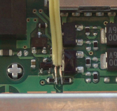
On this picture the joints are covered with transparent non-conductive glue to prevent possible damage from accidentially pulling the wires. The SL-C1000 is shown, but the PCB design is shared between all PXA270-based Zaurii - C1000/C3000/C3100.
Since the port1 has differential data lines, the wiring schemantics could be as simple as the following:
____________                            ____________
|          |                            |          |
|     D+  o------------------------------o  D+     |
|     D-  o------------------------------o  D-     |
|          |                            |          |
|     VCC o------------------------------o  VCC    |
|     GND o------------------------------o  GND    |
|          |                            |          |
|   HOST   |                            |  CLIENT  |
------------                            ------------
assuming that VCC is provided by the HOST - Zaurus.
Here's something that looks awfully like the pin-out of Mitsumi WML-C19 bluetooth module used by Sharp in Zaurus SL-6000 series:
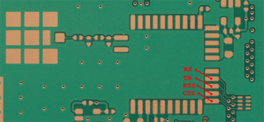
Please note that on the picture above RX is connected to BTUART's TX and vise versa, so no crossing over is necessary. The same is true for CTS and RTS.
To enable traces to Mitsumi WML-C19 pads, the following contact points need to be connected in the CPU compartment (located under the metal shielding) with a resistor array (Intel recommends to use 10 - 25 Ohm nominal resistance in [1] on p.20-2):
BEFORE |
AFTER |
|---|---|
 |
 |
If BTUART is not used or used with BCSP protocol of CSR-based bluetooth module, then CTS and RTS lines can be re-purposed as GPIO pins 44 and 45.
The Zaurus has dedicated 5V OTG power domain to power up devices connected to the USB OTG connector. It uses TOKO's TK3850 5V voltage regulator with input voltage drawn from 5V domain. There's a cut-off over-current protection @ ~200mA implemented by a 5.7K resistor on TK3850's PCL pin.
This limit could be lifted to:
There's no cut-off limit if PCL is grounded. According to TK3850's datasheet there's a ~170mV voltage dropout @ 500mA load.
Here's what the datasheet says about power dissipation on p.4:
Expected power dissipation is 1.1W or less when mounted on a PCB substrate. Instantaneous power dissipation due to short circuit can reach 13W when the input voltage is 12V or more. This condition creates a very rapid temperature rise and may result in the chip catching on fire. When experimenting with this part please note that there is no instantaneous short circuit protection if the input voltage is 12V or more and the PCL function is not being used. However, if the short-circuit current is set to 500mA or less by using the PCL function, nothing will be damaged because the maximum input power is limited even when the input potential is high. (If the input voltage goes up, the output current increases, or the ambient temperature rises the internal thermal shutdown sensor will protect the IC). When the thermal sensor works, the regulator will shut off. As the junction temperature decreases, the regulator will begin to operate again. Under sustained fault conditions the regulator output will oscillate as the device turns off then resets. Please improve heat radiation or lower the input electric power.
According to the following post by Boris, it should be safe to draw ~500mA from this regulator. I'm using it with a 1K resistor on the PCL pin, and it's able to provide sufficient current to power both internal Wi-Fi and bluetooth modules at the same time.
Here's a picture of 5V OTG power regulator:

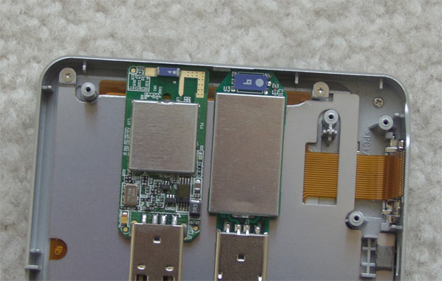
The following two modules were used in this project: the old revision of CSR BC02-Ext-based USB bluetooth 1.1 dongle from Billionton and an unexpensive ZyDAS ZD1211-based 802.11b/g USB dongle from Zonet:


There's a CF card underneath the modules, so you can see how it compares size-wise.
Here's another shot showing how does it fit into Z's compartment:

ZyDAS has linux drivers available here. While the driver is rather fat, messy and undocumented, it seems to be getting somewhat stable lately. It supports both 2.4 and 2.6 kernels, WPP/WPA2, master and monitor modes. While ZD1211 chipset supports all 802.11a/b/g freq's and modulations, the driver will work in 802.11b mode only if attached to USB 1.1 bus. With theoretical throughput of 12Mb/s, USB 1.1 effective transfer rate would max out at ~8.8Mbit/s (but could be worse in practice), so there's not much room even for 802.11b. A word of caution about Zonet ZEW2501 dongle - there was a report on zd1211-dev list that Zonet now manufactures a new revision that uses ZD1211B chip instead of old ZD1211, but plastic casing looks the same. The new dongle's usb vid/id is 0x0ace:0x1215 while old one's is 0x0ace:0x1211.
CSR BC02-Ext is well supported in Linux bluetooth stacks - BlueZ, Affix and OpenBT. It can be used with proprientary BCSP serial protocol, which essentially allows to get away without using hardware flow control, and thus re-purpose CTS and RTS lines on Zaurus as GPIO pins 44 and 45. Since it's sold as an USB dongle, it uses USB interface by default, but could be re-programmed to switch to serial UART interface. I used the same module before in the following projects: Psion5mx and Simpad. The other thing to note about CSR modules is that they have so-called "deep-sleep" power saving mode which can be enabled by sending break signal. Also this module has a dedicated reset line, which can be controlled by GPIO pin.
bccmd from bluez-utils package was used to switch the module from USB to BCSP UART protocol. This module works fine @ 921600 baud with BlueZ on the Zaurus. The module pinout can be found here.
The small cut was done in metal shielding that lays under the keypad to reduce blocking of RF signal. Here's how this opening relates to antenna's locations:
Here's the picture of assembled PCB:

There's a LED wired up to ZD1211 with flying leads:


Here's a view from the other side:

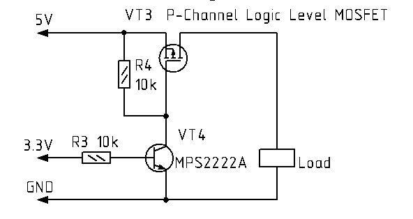
Since after trivial resistor replacement modification the 5V OTG power regulator is able to provide sufficient power for both bluetooth and wi-fi dongles, I was using its output to power up internal modules. The following schemantic (thanks to Boris) is used to control the power to individual modules:
I've never used the Zaurus as an USB client (nor have any desire to do that in future), so I decided to drop usb client functionality completely and to change the Sharp's OHCI glue driver accordingly. The new driver is a drop-in replacement for the old one and available here. It frees up two extra GPIO pins (GPIO41 & GPIO35) which can then be re-purposed.
A few things to note when using this driver:
Also control over the 5V OTG power domain is now separated from the driver and is implemented as a userland utility available here.
Sharp's serial driver is not quite up to the task. The "de-sharped" driver is available here.
Here's some small pieces (mostly clean-up) to Sharp/Lineo's messy kernel code.
I decided to keep USB OHCI driver loaded and 5V OTG regulator powered when Zaurus is not suspended. Here's a relevant snipset from /etc/rc.d/rc.rofilesys:
/sbin/powerctl bt   off  >/dev/null 2>&1
/sbin/powerctl wifi off  >/dev/null 2>&1
modprobe usb_ohci_pxa27x >/dev/null 2>&1
/sbin/powerctl otg  on   >/dev/null 2>&1
With individual modules power turned off, drain from 5V OTG regulator seems to be insignificant, also it's a matter of conviniece since external USB client devices can be plugged/unplugged at any time.
PM suspend/resume events seems to be handled by both USB OHCI and serial drivers quite well, the only thing I had to add is the following /etc/scripts.d/otg script to control 5V OTG power regulator on suspend/resume events (it's symlink'ed to /etc/apm/suspend.d and /etc/apm/resume.d directories) - I believe it might be because of a timing issue with hotplug, i.e. if I turn off 5V OTG from the USB OHCI driver on PM suspend event, the hotplug script didn't have sufficient time to complete before resume event happens and the other hotplug scripts has to run. So, scheduling it's via /etc/apm scripts gives it more time (barely enougth in my case) to finish the job between suspend and resume events.
Wi-fi module initialization is handled by USB hotplug and triggered by powering up/down the module. Bluetooth uses the following /etc/rc.d/init.d/bluetooth script. On suspend the module gets reset, but since BlueZ can only establish BCSP link using userland utility (hciattach), this script is also symlinked to /etc/apm/suspend.d and /etc/apm/resume.d directories to handle link re-establishment.
During suspend all clocks are turned off by both OHCI and serial driver as well as power to 5V OTG regulator.
I hacked a XFCE 4.2 panel plugin to control the power of internal modules from XFCE4 panel.
There're a few things worth to notice about SL-C1000:

I'm using these two GPIO pins on my C1000 to control power from 5V OTG regulator to internal Wi-Fi and bluetooth modules and it doesn't seem to interfere with anything on C1000.
Below are some small bits and pieces which I didn't personaly use and thus didn't have a chance to test out. I have reasonable belief that it might be useful, but please test it before trying to use, since it's untested at the moment.
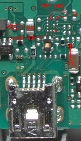
There're two GPIO's traced to test/debug pads. They don't seem to be used in the Linux kernel on Zaurus, but mught be used by Sharp's bootloader or testing/maintenance software:

Here's some GPIO pins used by Sharp's OTG implementation. In order to re-purpose GPIO41, R1 resistor needs to be removed to disconnect the line from the OTG connector.
It's possible that 5V could be found on pins 1,2 and 3 of LCD connector (please test it before using, since it's untested at the moment):

EOF
Did you find this information useful? Please consider donating to the cause of exploration...
You can reach me at albertr at iral dot com.